

Physical Design and Installation
Overview
N.B. Solar installation requires working with dangerous electrical currents. These may be life threatening and/or may severely damage and destroy property.
Additionally, solar installation requires physical modifications to your caravan that may void your insurance and/or result in damage. The physical installation may also result in personal injury.
Take all safety precautions and seek professional/expert assistance if uncertain.
Whilst all care has been taken in preparing the following, it may contain misinformation, errors and omissions. No responsibility is accepted for any damages, personal injuries or ill effects. You have been warned!
Any work on 240 volt systems must be carried out by certified personnel. Having said that, a solar installation should be within the capabilities of most, experienced handymen.
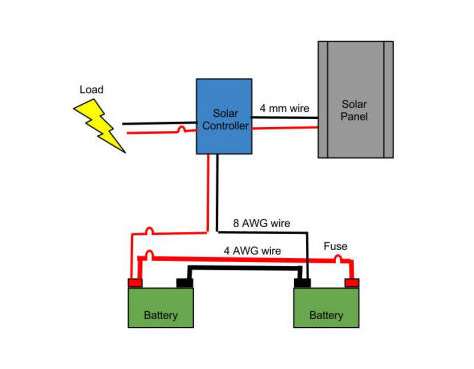
The following shows the typical wiring requirements for a solar installation:
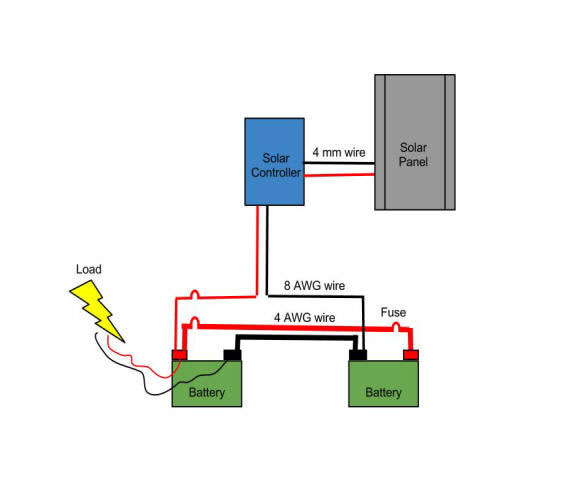
Obviously the Solar Panel will be mounted externally, nominally on the caravan roof, and all other components in a dry location, protected from the weather.
Batteries
Only use Deep Cycle Batteries. You will need to purchase these from a battery specialist. Try http://www.batteryworld.com.au/ or http://www.burson.com.au/. (You can also use a Gell Battery but these are more expensive and require a more specialised Solar Controller for charging. Do not use a Starting/Cranking Battery as this will rapidly fail.) If you're buying new batteries and are particular about what you buy you may like to try http://www.batteryvalue.com.au/ located in Brisbane. Deep Cycle batteries tend to have a lower stock turn over at dealerships which results in 'ageing', purchasing batteries stocked 'fresh from the factory', as Battery Value claim, may provide additional value (in addition to BV's attractive prices).
Most modern batteries are 'sealed' and may be installed within the caravan's internal living space; although some external ventilation remains desirable (reference). Otherwise they must be installed in a ventilated, weather proof, external location. If your batteries have screw caps giving access to topping up battery fluid levels or any other form of physical access to the internal workings; they are not sealed and must not be installed internally. Sealed batteries will likely also state they can be mounted in any position. Check with your supplier if uncertain. In the following, it is assumed your batteries are of the 'sealed' variety.
Which battery type should I use? Here is a comparison of battery types. In the context of this article, bear in mind that power from the sun may be intermittent and you will want to capture as much power as possible when it is available. For this reason, AGM batteries are recommended as they charge rapidly; and are all of the sealed variety. (Gel batteries also charge rapidly but are significantly more expensive and mostly of lower capacities). Whichever battery type you use, ensure your charging capabilities (solar controller and/or caravan charger) accommodates that battery type.
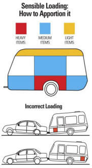 Batteries are heavy and should be mounted low in the caravan and as close above the caravan's axle as possible. Additional, they should be balanced (or counter-balanced) left/right across the axle.
They must be securely mounted to prevent any forward, aft or sideways movement; and strapped down to prevent any vertical movement. Vibration can also be an issue and in extreme conditions can cause battery cells to collapse and short circuit. If this is a concern to you then consider Optima Yellow Top deep cycle batteries (although these have lower capacities and there have been reports of abrupt problems; don't know how common).
It is likely that your caravan will have an existing battery and in this situation you will be installing a second. In this case, it is probably best to leave the existing battery where it is and mount the second battery as just described, where it will counter-balance your water storage, or other heavy above-axle weight, as best as possible. Bear in mind that when you connect the batteries you will want to keep the wiring as short as possible (see below).
In general, keep your caravan's centre of gravity as low as possible and distributed evenly (left-right) above the axles. You also want about 10% of your caravan's weight over the hitch; and that tow-ball/hitch weight should not exceed your towing vehicle's tow-ball load specification.
Installing a Second Battery
You can install a second battery as Phase 1 of your Solar Installation. This is a relatively straight forward step and can be done independently of a Solar Installation. However, be aware of your caravan's battery charging capacity. If you do not proceed with the Solar Panel Installation, you should upgrade your caravan's battery charging capacity. Nominally your charger's amperage should be about 10% of your battery's amperage hour capacity. For example, use a 10 amp charger on a 100 Ah battery ref, etc.
Decide where to place and securely mount your second battery, as discussed above; then connect it as per the wiring diagram, also as above, as shown using 4 AWG cables. When purchasing these cables (try http://www.repco.com.au/), they may be described by their Amp rating. You will likely want 215 or 250 Amp cables (note, suppliers' Amp ratings tend to be optimistic and probably double that required of a constant load; AWG ratings are more specific). The greater the distance between your batteries, the higher the Amp rating you will want. If you can locate the batteries side-by-side, you can purchase and connect them using copper 'straps' as a preferred alternative.
4 AWG Cables
 The 4 AWG cables are thick heavy duty cables and are used primarily to minimise voltage drop between the batteries. A voltage drop will naturally occur as current flows through a conductor (ie. the cable). It is influenced by the voltage (nominally 12 volts in this case), the conductivity of the connector and the length of the connector. Given that there will be some voltage drop, two batteries charged to exactly 12 volts each, will 'see' each other at less than 12 volts, and thus discharge to each other. Hence the use of heavy duty cables to minimise voltage drop.
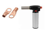
When you purchase the 4 AWG cables you will also want to purchase 'lugs' to go on the cable ends ends. You should be able to get these where you purchased the 4 AWG cable. Make sure the cable fits nicely into the lug and the lug will fit onto your battery's terminal. You will also need a blow torch to solder the cable into the lug (try http://www.jaycar.com.au/). Check out this video to see how to solder your cable and lug together: http://www.youtube.com/watch?v=q2XMkEGRzGU. If your lugs have holes on both ends, you will probably need to pre-solder (tin) the cables before inserting them, then fill the lug with solder. This will help prevent solder flowing out the bottom of the lug. You should crimp the cable/lugs prior to soldering (crimping will provide mechanical integrity and soldering, electrical conductivity; it is best not to rely on the soldering for mechanical integrity). You will need a heavy duty crimping tool (example) or use a hammer. You should also use Heat Shrink or electrical tape to properly insulate the cable/lug connection. Use washers to connect the lugs to the battery/fuse terminal if the lug holes are too big.
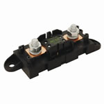 When connecting your batteries you will also want 2x high-amperage inline fuses. These must be connected, as shown in the wiring diagram, as close to each battery's positive (red) terminal as practical. Be particular about these fuses as you want them to provide high conductivity.
Some fuse holders provide screw-down connectors for the cables - I would not recommend them. A good fuse holder is shown on the right hand side and requires cables to be connected via lugs (as discussed above).
Try http://www.jaycar.com.au/productView.asp?ID=SF1980 for these. They are also known as 'mega-fuses'. You will want 125 amp fuses to go with these. The objective of these fuses is to protect from short-circuits originating from the heavy duty cable - not from the load drawn by the caravan. Buy a couple of spare fuses in case you need them whilst bush (hopefully you will never use them). Also make sure you have sufficient cable lugs to connect the fuses.
It is important when making connections that everything is done to ensure they are highly conductivity, durable and robust. If passing any cables or wiring through panels, always use grommets to help protect the cable/wiring from abrasion. Also, any cabling/wiring exposed to the elements should be routed through weather proof conduits.
Take care when making the final connections to the batteries. Ensure that the batteries are equally charged (nominally about 12.7 volts each). The cables are connected from each battery's positive (red) terminal to positive terminal; and each negative (black) terminal to negative terminal. Connect the black, negative cables first, both the fuse holders and red, positive cables then plug in the fuses last.
Solar Panel
Note: Have a look here for your solar panels and controller:
Sola Connections: (Note: They have moved and web site is a bit out of date. Best to call on (03)9768 9420. They are located at Factory 20, 25 Bald Hill Rd, Pakenham VIC). In the interests of full disclosure: I purchased my gear from them and found them to be extremely helpful in advising a complete package, plus additional bits and pieces, such as connectors; and at a good price. I do not have any other interests in Sola Connections.
Another vendor you may like to try is Hye Trading Power located in Croydon, VIC. They carry a wide variety of low power product including Solar. Being in Croydon many members may find that more convenient.
Okay, so you've read How Much Power and figured your solar panel sizing (watts). Solar panels come in various sizes and wattages, however, for the purposes of this discussion we will focus on 120 watt and 240 watt panels (we will also only discuss monocrystalline solar panels) as these represent typical installations.
If you do require a 240 watt size solar panel, you then have the choice of 2 x 120 watt panels or a single 240 watt panel. In this case, a single, albeit, larger panel is recommended, mainly because it will require less work mounting. More importantly, with a 240 watt panel you may have the option of either a nominal 12 volt or 24 volt panel. A 24 volt panel is recommended because under low light conditions it will provide a usable current for a somewhat longer period. Additionally, a 24 volt system will experience a lower voltage drop between the panel and controller, although that is a marginal benefit. (If opting for a 24 volt panel, it must be matched to a 24 volt solar controller, see below.)
N.B. If you plan to connect multiple solar panels together, they must be of similar specifications; otherwise power will be pushed to the smaller panel.
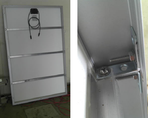
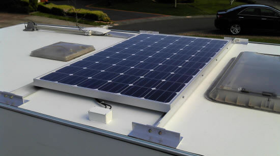
Before mounting your solar panel, you may first need to strengthen the panel's underside. Typical solar panels are not designed for mounting on caravans that are consistently subject to 100kmh winds and side buffeting. The larger your panel the more significant this issue. The following pictures show the under-side of a 240 watt panel that has been strengthened using three 'H' beams (running left-right in picture), siliconed to the panel underside and then secured on their ends to the panel's frame using little 'L' brackets:
In order to mount the solar panel on your caravan roof you will want to mount it on a frame that will be attached to the caravan's roof. It is easiest to measure up where you want to mount the panel/frame on the caravan's roof then construct and assemble the entire setup in your workshop.
When deciding where on the caravan roof to place the panel, consider where you will anchor the frame to the roof (probably using an adhesive, as discussed below), clearance from any obstructions and wiring through to the solar controller. (Also read section on solar controller placement before deciding where to place the panel.) Note that the frame's anchor points should be as close as possible to other structural components on the caravan's roof, e.g., near the edge, and/or above internal wall supports if you can locate them. Additionally, you will want a reasonably low profile exposure to the wind in order to minimise wind resistance and overall structural load. If necessary consider streamlining the leading edge. Attempting to build in legs, or other such adjustable devices, in order to 'point' the panel to the sun will complicate your design, place additional stress on components and is unlikely to achieve worthwhile benefit.
After you have decided where to place the panel on the caravan's roof, you must then design the panel's roof mounting frame. When designing the frame:
- Allow for some ventilation space under the mounted panel and between the caravan's roof. Although solar panels are most efficient at about a temperature of 40C, this represents the panel temperature, not the ambient temperature. Hence ventilation is essential for optimal efficiency.
- Remember that at some point you may need to replace the solar panel and a frame that can accommodate some variability in panel size is desirable.
- Ensure the frame design enables easy access to solar panel mounting points after it has been anchored to the caravan. You must be able to remove and replace the solar panel without removing the frame from the caravan. Inaccessible nuts and bolts will prohibit this.
- Above all, the caravan must structurally support the frame, and the frame must structurally support the panel's weight and withstand 100kmh plus winds; for the life of the installation.
The following pictures show a panel attached to a frame prior to mounting on the caravan's roof; and a close-up of the roof anchor point assembly. The frame was constructed using 50x50mm aluminium 'L' beams and all nuts secured by ThreadLoc or Nyloc nuts.
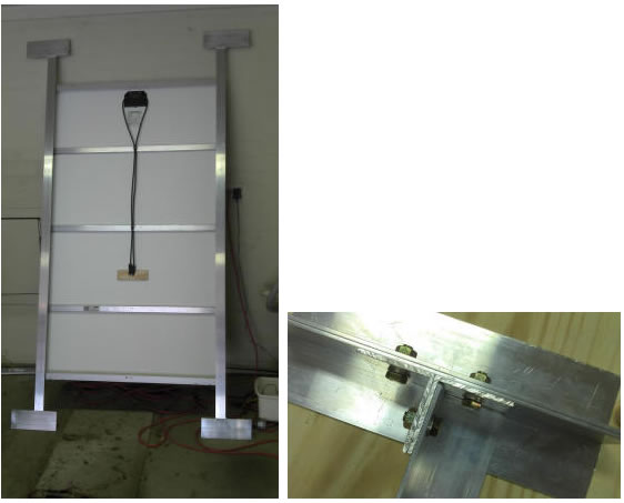
N.B. The above pictures only provide an example. You must decide what is required for your installation which will likely vary considerably.
When mounting you solar panel frame assembly, it will be easiest to mount it as an assembled unit (rather than mounting the frame then attaching the panel to the frame when on the caravan).
 Depending on your caravan/frame mounting options, you may need to use an adhesive. The recommended adhesive is Sikaflex-227 that is available from Bunnings: http://www.bunnings.com.au/ (look in the paint section) and automotive stores. It is similar to Liquid Nails (made by Selleys) but, importantly, retains its flexibility (note - do not use Liquid Nails, it will not retain its flexibility). Follow instructions on the Sikaflex packaging and ensure the surface of your caravan's roof is properly prepared (clean, dry and free from oil, etc).
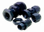 After mounting your solar panel, you will also need to wire the solar panel cables through the caravan roof, wall ,etc, to the solar controller. In the following picture, an aluminium project box from http://www.jaycar.com.au was used (drill required holes into sides and bottom, then through caravan; ensure cables are protected from abrasion; fill entry hole into caravan with silicon or similar) and is visible near the foreground. The solar panel cable entry into the project box is via weather proof cable glands (see picture above, left; refer http://www.jaycar.com.au/productView.asp?ID=HP0720&form=CAT2&SUBCATID=996#1). The project box is secured to the roof using Sikaflex-227 ensuring a weather proof seal around the bottom.
Solar Controller
Power from the solar panel arrives at the solar controller in a 'raw' form with a wide range of power and volts. The solar controller converts this into a current that is used to charge your battery. At the same time, most solar controllers allow you to directly draw current from it via its Load Output. Consequently most solar controllers of interest in this discussion will have cable connectors for:
- Solar panel input,
- Battery connection, and
- Load output.
If you look at the Wiring Diagram at the top of this page you will notice that Load is being drawn from the Battery (not the Solar Controller). This is the easiest way of wiring up the system, however, later we will discuss how Load may be drawn from the Solar Controller.
Because power can flow in either direction between the battery and controller, this connection must be protected on both ends from short circuits (assuming the battery and controller are separated by some distance).
The controller should have built-in short circuit protection so a fuse near the controller should not be required (check your controller's manual and install a similar fuse, as per following, near the controller if required). In any event, a fuse should be installed near the battery. This fuse should be rated to the controller's nominal charging capacity (probably either 10-15 or 20-30 amp; based on a 120 watt or 240 watt solar panel and matched controller).
If you do decide to draw power from the controller's Load Output, as discussed below, you may want to increase the fuse rating to the surge rating of the controller's Load Output (probably about 30% to 50% above the standard load rating).
The fuse holder 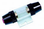 you use for this connection (battery/controller) should be of a lower rating than the battery/battery connection (mega-fuse) discussed above. Refer picture on right as an example. These can be purchased here: http://www.jaycar.com.au/productView.asp?ID=SZ2060
Note that the exact type of fuse holder does not really matter - it's really only driven by availability of fuses (and wire dimensions) to match the current amperage you are protecting against. Other fuse holder designs are available. You just need to check that corresponding fuses, within the range you require, plus some leeway, are (readily) available. It's also a good idea to purchase a few spare fuses and hope to never use them.
When you purchase your Solar Controller, you have the following primary decisions (apart from price):
- Solar controller solar panel capacity,
- Solar controller technology (PWM or MPPT), and
- Battery charging technology (3 to 5 stage charging).
The most important is matching up controller capacity with your power requirements. Generally, for a 240 watt solar panel you will want a 20 to 30 amp solar controller; and for a 120 watt system you will want a 10 to 15 amp controller. The higher capacities provide some 'head space' in the system which should provide a less stressed (more reliable) component, especially in the longer term.
If you opted for a 24 volt solar panel then your solar controller must accept 24 volt solar panel input. Most '24 volt' solar controllers will auto detect 12 or 24 volt solar panel input and output to a 12 volt system but you do need to check this.
Solar controller technology in this (consumer) space is divided between PWM (Pulse Width Modulation) and MPPT (Maximum Power Point Tracking) technologies. As can be expected the newer MPPT technology is more expensive but more efficient, especially when higher currents are involved. A PWM controller can also cause interference to your TV, etc. You can watch a video here if you want to know more. For a 240 watt system, the additional investment in a MPPT controller is probably worthwhile when viewed against overall system cost. For a 120 watt system, you may want the additional efficiency to help 'enlarge' a smaller system size. In practice, it is only going to make a difference during periods of inclement weather.
A primary function of a solar controller is to charge your batteries. Given that a good 100 Ah battery can cost several hundred dollars, you will want a solar controller with a battery charger of commensurate quality. Battery chargers are generally described by the number of charging stages they support, anything from 2-stages to 5-stages, or more. Basically, the more the better, however most caravan systems cannot justify chargers that support stages past 4 or 5. The minimum recommended is a 3-stage controller (although a 2-stage will work adequately). 4/5 stage controllers provide for battery cell equalisation and de-sulfation. These capabilities will extend the life of your battery however there comes a point when the cost of the battery charger cannot justify any cost recoverable from an extended battery life.
It is advisable to seek advice in regards Solar Controller reliability and, avoid generic brands and bargains as this component is likely to be the weakest link in the system. (To determine if a brand is 'generic' try Google-ing it and possibly your model, looking for a global reputation. Read independent reviews if available.)
Your solar controller should come with mounting instructions describing how and where to mount it. Generally this will focus on environmental protection and air circulation; and these instructions must be followed. Where you have installed your batteries and solar panel, will help determine where you mount your solar controller. Additionally some solar controllers come with remote display panels and this may ease mounting constraints; otherwise access to the controller will be a higher consideration. The following picture shows an internally mounted controller with more than the required ventilation space.
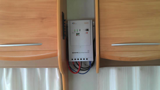
In the above, the black cables lead from the solar panel. The red and black cables lead from the battery and the blue cable leads from a remote display. The unused connector is the Load Output.
Once the solar controller is mounted, what remains is to connect all the cables. The hard part of this is the monkey work involved in routing them all nicely.
When wiring the battery cable to the controller, note how it is shown in the wiring diagram at the top of this page. Here 8 AWG wiring is used. This is a relatively thick cable but mush less so than the 4 AWG cable used to connect the batteries. Also note how it is connected - that is, in a dual battery system, the positive is connected to the positive of one battery and the negative to the negative of the other battery. Whilst the controller need only be connected to a single battery in a multi-battery system, connecting the controller to the ends of a battery bank provides for a more even charge and discharge.
Also note how the Load is shown connected in the wiring diagram. It shows how a caravan's existing wiring is probably connected in a single battery setup. A preferable approach is similar to what was just described (when connecting the controller) whereby a multi-battery system is treated as a single battery bank. That is, connect the load across ends of the battery bank - positive to one end and negative to the other. Also try to keep the negative and positive wire lengths short but of equal lengths (it is better not to run a long single wire to reach the far battery).
Important: when connecting cables to the solar controller, they must be connected and disconnected in a specific order! Your solar controller instruction manual should describe this process and that should be followed. Failure to do so may result in a blown fuse or worse. The normal sequence is:
- Connect the battery first (this will power up the controller and activate its protection mechanisms),
- Then connect the solar panel, and
- Lastly, connect the Load Output.
Disconnect in reverse order.
(Ideally you should block light to the solar panel before connecting it at Step 2, or do this at night, then allow light to the solar panel, after the Load Output has been connected. It is also preferable that your battery is fully charged as the controller may use its voltage as an initial reference point.)
Congratulations! At this point you have installed a typical caravan solar power system. Read on, in order to understand how to take it a step further.
Load Output
The only thing remiss in the above installation is the unused solar controller's Load Output connection. There are pros and cons to using the solar controller's Load Output.
The main benefit is that the solar controller is better able to manage the battery, mainly the charging. When drawing power only from the controller's Load Output, the controller will better understand where in the charging cycle the battery is. It will not be 'confused' by load being drawn off the battery.
Additionally, whilst solar power is available (as in, during the in day), power to the Load Output can be supplied directly from the solar panel, rather than firstly drawing down the battery. Most controller's Load Output will also disconnect if the battery voltage drops too low, thus protecting your battery. Some controllers will also display instant and accumulated values for current drawn from the Load Output. This can be useful in managing your power consumption (TV, lighting, charging, etc).
The downside of using the solar controller's Load Output is that some high surge appliances might overload it. The most likely example to be found in a caravan is probably a compressor based refrigerator and (12 to 240 volt) inverters. For most installations this is unlikely to be an issue or can be easily worked around (connect these appliances directly to the battery).
The main drawback is probably the installation. The issue here is that connecting the Load Output requires rerouting the caravan's existing wiring which may include existing battery charging capabilities. Because of the variety of caravans around there is no general solution and each caravan must be considered individually. Also, by following the approach below, you may lose the ability to charge the battery via the 240 volt system.
If you decide to proceed, re-read the disclaimer at the start of this article; and proceed with caution. If you are not clear about what is discussed below and/or cannot clearly identify wiring as described below, then seek expert/professional assistance.
You will need to examine your caravan's existing wiring, paying particular attention to connections to the battery and from the 240 volt charger. Ensure your caravan is not plugged into the 240 volt system when working with 240 volt components or connected components; and do not tamper with the 240 volt wiring.
Note: in the discussion that follows:
- The term 'existing wiring' refers to existing 12 volt wiring running throughout the caravan but in the following paragraphs, the term refers more specifically to the 12 volt wiring behind the caravan's fuse box assembly and, for this discussion, it is considered a 'black box' - we don't know what's happening inside. The fuse box assembly should be in close proximity to the charger and battery.
- During the following installation, if you proceed, be sure to fasten any disconnected wiring safely and securely. It will be best to replace any cuts and joins, with plugs such that the wiring can easily be reconfigured, back to previously, at a later date if necessary; For example, if you put into a caravan park during inclement weather or want to increase your 12-volt consumption whilst 240 volt power is available. Remember to clearly label all wiring ends for easy identification later. Better still, make yourself a wiring diagram (with clearly labelled connectors) or take photographs, showing both configurations.
240/12 volt Battery Charging:
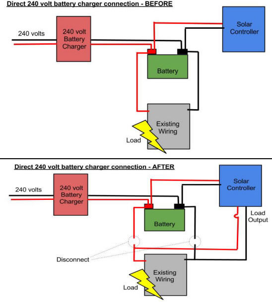
Your caravan's battery charger might or might not be connected directly to the battery. If it is directly connected to the battery (refer diagrams below) it can probably remain as is; however bear in mind its charging capacity if you have also installed an additional second battery (ie. you require about 10 amp for every 100 Ah of battery capacity).
Otherwise, if it is indirectly connected to the battery (refer diagrams below), as is likely, the 'charger' is probably only a step-down transformer and battery management is being performed within the existing wiring. In this case you should be able to simply disconnect the existing battery charger, from the battery AND existing wiring.
The basic issue in respect to the 240/12 volt charger, is preventing current flowing backwards into the controller via its Load Output (i.e. if 240 volt charging is left connected via existing wiring and load is taken from the controller's Load Output, current may flow into the controller's Load Output - not good). Your controller's Load Output may or may not, be able to accommodate a back flow of current (unlike the controller's battery charger that is designed for this situation) and specifications in this respect may be difficult to determine. Although other solutions are possible, the above is recommended as it is the most simple, conservative and reliable, generic solution; and given that you now have solar power, the need for additional 240 volt charging should be minimal.
If you are following the 'indirect connection' scenario, as below, and do want to maintain the ability to charge your batteries from the 240 volt grid then the safest and simplest option is to connect a regular 240/12 volt battery charger to your batteries and plug into the 240 volt system when required. Bear in mind the charger should be rated to about 10 amp for every 100 Ah of battery (bank) capacity (if running an additional, second battery, your existing 240 volt charger may be under-rated).
Load Output:
The caravan's existing wiring should connect directly to the battery (to supply power) and you should be able to:
- Disconnect the existing wiring (load) from the battery, and,
- Route it to the solar controller's Load Output.
When connecting to the controller's Load Output you should use 8 AWG wiring. You should also place a fuse on the positive (red) wire close to the solar controller (see below). The fuse amperage should match the Load Output's rated surge capacity. As per disconnecting the 240 volt charger, use plugs to facilitate, later, ease of re-configuration; and clearly label all ends.
Your caravan's existing wiring should have a battery isolation switch located somewhere convenient. If installing the wiring as per diagrams below, you should check that you do not inadvertently bypass the battery isolation capability. If uncertain, then check if your solar controller has a Load Output 'off' switch. Alternatively you should install one on the positive wiring of the Load Output. Similarly, if you are drawing power directly from the battery (bank), for example, to power high current appliances, check that the battery can conveniently be isolated from these as well. Nominally, your battery (bank) should be isolated (from power consuming devices) when your van is in storage (but continue battery charging/maintenance).
Direct 240 volt charger connection summary:
If your 240 volt battery charger is not clearly 'directly connected' as per above diagram then the following 'indirect connection' might apply. Bear in mind that wiring diagrams do not necessarily reflect actual wiring. If you find the previous statement confusing it is important that you seek expert advice
Indirect 240 volt charger connection summary:
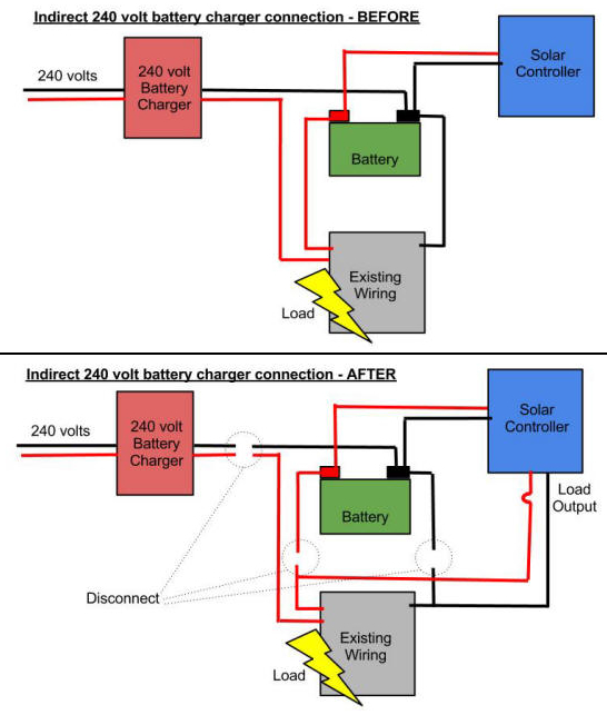
The end result should look like this (ignoring the 240 volt battery charger):
In summary, disconnect the 240 volt charger (if it is an indirect connection to the battery) from the battery and existing wiring; then disconnect the existing wiring (load) from the battery and route it to the solar controller's Load Output with a fuse near the solar controller.